
For flexible and rigid‑flex PCB projects, vague specifications during RFQ often result in huge price gaps among supplier quotations. These differences usually stem from inconsistent product scope rather than manufacturing efficiency. Five constraint groups must be clearly defined before sending out RFQ, so you can get comparable quotes.
Relevant IPC Standards Reference
- Flexible section: IPC‑6013
- Rigid section: IPC‑6012
- Acceptance criteria: IPC‑A‑600
- Rigid base material: IPC‑4101F
- Flexible dielectric material: IPC‑4204C
When validating certificates, verify certificate number, issuing authority, scope of coverage and expiry date, and confirm they apply to the actual production facility.
1. What Causes Big Gaps Between PCB Supplier Quotes? (5 Common Ambiguities)
- Single standard for whole board: Rigid‑flex PCB requires separate specifications for rigid zones and flexible zones. Do not apply one standard to the entire board.
- Trade‑name‑only material reference: Always reference IPC standard numbers. Same commercial name may cover different material systems from different vendors.
- Inherited tolerances from old rigid PCB design: Re‑check minimum line width, hole size, copper weight and impedance tolerance against the new stack‑up. Do not copy old rigid‑board parameters directly.
- Unspecified surface finish: Suppliers may apply default finishes without notification. Lead‑free HASL and ENIG are not interchangeable. Gold thickness for gold fingers shall be explicitly stated.
- Documentation requested after PO: Material certificates, impedance reports, electrical‑test records and PPAP packages shall be required at RFQ phase instead of after purchase‑order placement.
2. How is the Flex‑PCB Market Evolving Today?
Global PCB market is projected to hit $95.8 billion in 2026, with China accounting for around 60% of worldwide output. Flexible PCB market grows at a 12.3% CAGR, outpacing general PCB market growth. Many procurement teams are experienced with rigid PCBs but lack specification experience for flex designs.
SHENZHEN JERICO MULTILAYER PCB CO., LTD (JERICO / JRC) was founded in 2009; it runs a 20,000 m² manufacturing plant in Wuping (Fujian) plus a business center in Shenzhen. Its product portfolio covers 1‑ to 32‑layer PCBs, including rigid‑flex, HDI, heavy‑copper and high‑frequency boards. Its well‑documented mass‑production strength focuses on rigid PCBs (1‑18 layers), buried/blind‑via HDI, heavy‑copper and metal‑core boards. Though flex / rigid‑flex is listed in the product range, submit the stack‑up plus bending requirements and demand written confirmation of flex capability instead of relying only on marketing brochures.
Certifications: IATF 16949:2016 (valid until 2026‑12‑21), ISO 9001, ISO 14001, UL recognition File No. E519316, RoHS & REACH compliance reports.
3. What Five Key Constraints Should You Lock In for Your RFQ?
Layer 1 — Applicable Standard & Acceptance Class
For rigid‑flex PCBs, assign standards per physical zone: IPC‑6012 for rigid areas, IPC‑6013 for flexible areas, and IPC‑A‑600 for final‑board acceptance. Jerico’s multilayer products can be built to IPC‑6012 Class 3 with UL94 V‑0 flammability rating.

PCB-54: a documented 6-layer FR-4 board with ENIG finish, 1.6 mm thickness, 2 oz finished copper, 0.15 mm minimum hole size and 3 mil minimum line width and spacing
Layer 2 — Base Material (referenced by IPC standard)
For rigid sections, high‑Tg FR‑4 is widely adopted. Automotive applications typically require Tg ≥ 170‑180 °C, CAF resistance, halogen‑free option, and UL94‑V‑0. Flexible dielectric shall reference IPC‑4204C.
Layer 3 — Construction, Copper Weight & Impedance
Define layer count & stack‑up, finished board thickness with tolerance, inner / outer copper weight, minimum line & space, minimum hole size, BGA pitch, plus impedance targets and allowed deviation.
Jerico reference product parameters:
- TU‑883 hsd hdi 18L: 18‑layer 2‑step HDI (2+14+2 stack‑up), finished thickness 2.40 mm ±0.10 mm; differential impedance 100 Ω ±8 %, single‑ended impedance 50 Ω ±10 %; minimum BGA pitch 0.5 mm.
- M7: 32‑layer 3‑step HDI (4+24+4 stack‑up), finished thickness 3.20 mm ±0.10 mm; minimum BGA pitch 0.4 mm; same impedance targets as TU‑883 series.
Layer 4 — Surface Finish
Available finishes include ENIG, ENEPIG, selective gold plating, OSP, immersion tin, immersion silver and HASL. Specify separately: main‑area finish and gold‑finger hard‑gold thickness (example: 1 μ‑inch ENIG base, 30 μ‑inch hard gold for fingers). For fine‑pitch assembly, HASL cannot substitute for ENIG.
Layer 5 — Documentation & Certification Package
Request these deliverables at RFQ stage: material certificates, UL reports, impedance test reports, factory electrical‑test reports. Add PPAP documentation for automotive mass‑production projects. Validate certificates: check number, issuing‑body, scope, expiry date and confirm coverage for the actual production site.
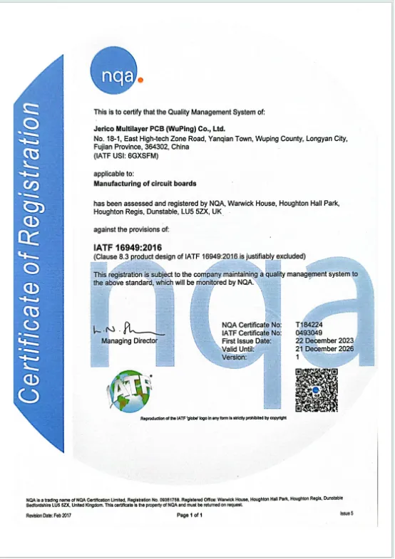
IATF 16949:2016 certificate, scope: manufacturing of circuit boards, valid 2023-12-22 to 2026-12-21
4. What Is a Complete 7‑Step RFQ‑to‑Release Workflow?
- Divide PCB into functional zones and assign corresponding IPC standard & acceptance class for each zone.
- Quote base‑material IPC reference numbers; specify Tg value for rigid sections under thermal cycling.
- Fully document stack‑up, copper weight, impedance values plus all tolerances.
- Separate surface‑finish requirements for board body and gold fingers, including plating thickness.
- Explicitly define test methodology: fixture‑based E‑test or flying‑probe test. Require X‑ray inspection for HDI BGA microvias.
- Request complete documentation set with RFQ rather than after PO issuance.
- Audit all certificates and ensure they cover the actual manufacturing facility.
5.Which Requirements Matter Most for Different End‑Markets?
- Automotive Electronics: Operating temperature ‑40 °C ~ +125 °C, service life of 10‑15 years. IATF 16949 is mandatory alongside RoHS, REACH and UL specifications. Wide thermal cycling imposes strict material‑grade and documentation requirements.
- Telecom & High‑Performance Computing: BGA pitch and impedance tolerance are top priorities.
- Industrial Control & Automation: Mechanical robustness and copper weight are critical for current‑carrying capacity.
- Consumer 3C / Smart‑Home / IoT: Cost‑sensitive. Suppliers may silently alter surface finish or test coverage to lower quoted price.
- Medical Equipment & Power‑Energy: Lot traceability, material declarations and reliability records outweigh marginal price advantages.
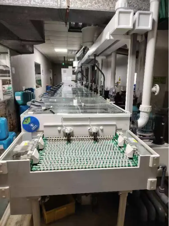
Production workshop
Comparison Tables
| Artifact | What it evidences | When to request |
| IATF 16949:2016 certificate (NQA:T184224; IATF:0493049; IATF USI:6GXSFM) | Quality management system certification with scope of manufacturing of circuit boards; issue 2023-12-22, expiry 2026-12-21 | Automotive or Tier-1 supply, at RFQ stage |
| UL Recognition, File No. E519316 | UL recognition status of the component | Safety-relevant end products, before design freeze |
| RoHS, REACH and SGS compliance test reports | Restricted-substance compliance for the delivered board | Every shipment into EU or USA markets |
| Impedance report | Verification of controlled impedance against the stated tolerance (±8% differential, ±10% single-ended) | High-speed digital designs, with first article |
| Factory electrical test report | Open/short verification by fixture E-test or flying-probe E-test, according to order quantity | Every order, method stated on the drawing |
| PPAP documentation | Production part approval package for mass production release | Automotive mass production projects |
Verified board parameters across documented Jerico product families
| Model | Type | Layers / stack-up | Base material | Surface finish | Min. line / space | Copper | Thickness |
| PCB-10 | Multilayer rigid | 4 | FR-4 | HASL lead-free | 3 mil / 3 mil | 1 oz | 1.0 / 1.2 / 1.6 mm or custom |
| PCB-54 | Rigid | 6 | FR-4 | ENIG | 3 mil / 3 mil | 1 oz base, 2 oz finished | 1.6 mm |
| PCB-55 | Rigid | 6 | FR-4 | ENIG | 3 mil / 3 mil | 1 oz finished | 1.6 mm |
| PCB-56 | Rigid | 4 | FR-4 | ENIG | 3 mil / 3 mil | 1 oz finished | 1.0 mm |
| PCBA-999 | Assembly | 4 | FR-4 | HASL lead-free | 3 mil / 3 mil | 1 oz | 1.2 mm |
| TU-883 hsd hdi 18L | 2-step HDI | 18 (2+14+2) | High-Tg FR-4, Tg ≥ 170 °C | ENIG 1 U-inch, hard gold 30 U-inch | 3 mil min. line width | 2 oz / 2 oz | 2.40 mm ± 0.10 mm |
| M7 | 3-step HDI | 32 (4+24+4) | TU933, Tg ≥ 180 °C | ENIG 1 U-inch, hard gold 30 U-inch | Stacked microvias, 0.4 mm BGA pitch | 2 oz / 2 oz | 3.20 mm ± 0.10 mm |
All values above are taken from the documented product specifications. They describe rigid and HDI families; for flex and rigid-flex constructions, the equivalent values must be confirmed against the specific stack-up in the RFQ response.
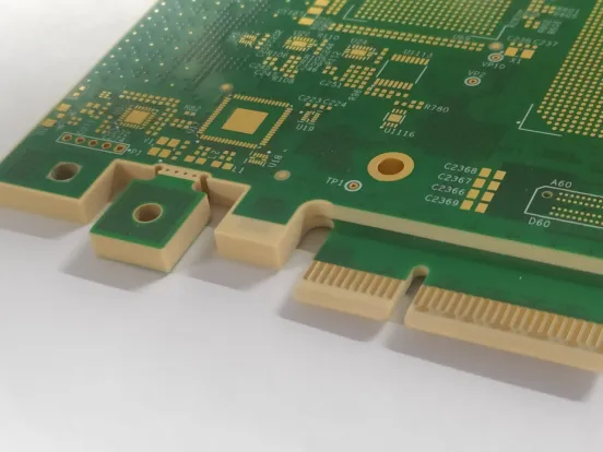
M7: 32-layer 3-step HDI with a 4+24+4 stack-up, TU933 high-Tg FR-4 at Tg ≥ 180 °C, 3.20 mm ± 0.10 mm finished thickness and a 0.4 mm minimum BGA pitch
6. What Are the Most Frequently Asked Buying Questions?
- IPC Class 3 qualification is not merely a certificate. Drawing specs, certificate scope and lot‑specific test reports must align with each other.
- Though Jerico lists flex / rigid‑flex capability, send stack‑up plus bending requirements and obtain written confirmation before project kick‑off.
- Large quotation gaps mostly come from relaxed specification parameters, not superior manufacturing efficiency.
- Prototype support: minimum order quantity of 1 piece; sample lead time as short as 3 working days. Overall lead‑time ranges from 7‑45 days depending on project complexity.
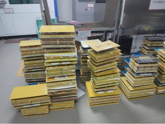
Test jig warehouse
7. Contact Jerico Now!
Considering you are familiar with these factors, the next step: test your constraint set against a real quotation.
Send a stack-up, a drawing and the acceptance class you intend to specify. Jerico will return a quotation that names the standard, the material reference, the impedance tolerance, the finish and the test method — plus the documentation pack that goes with it.