1. What is Conductive Anodic Filament (CAF) Failure?
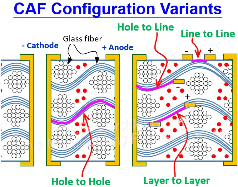
Conductive Anodic Filament (CAF) formation is an electrochemical process that leads to internal electrical shorts within a Printed Circuit Board (PCB). Under continuous DC bias voltage and high humidity, copper ions migrate along microscopic gaps between glass fibers and the epoxy resin substrate, moving from the anode to the cathode.
In other words, you can think of CAF (Conductive Anodic Filament) as “electrolytic corrosion” inside a PCB. Under long-term electrification and high humidity, minute copper ions migrate along the tiny micro-gaps between the glass fibers and resin matrix. They gradually grow from the anode to the cathode, eventually forming a microscopic “copper bridge” inside the board that triggers a direct short circuit.
What makes it particularly insidious is that it acts like a “chronic condition” occurring entirely below the surface.
The PCB passes factory 100% E-testing with zero issues, and functions flawlessly during customer assembly. However, after 3 months, 6 months, or a year in the hands of the end-user, the device suddenly suffers a catastrophic short circuit and board burnout. For procurement and quality managers, this kind of delayed failure is the absolute worst nightmare.
Which products are most vulnerable to CAF?
- Automotive & EV Electronics: Continuously exposed to high temperatures, high humidity, and high voltages.
- Industrial Controls & Power Equipment: Operating non-stop in harsh, non-climate-controlled environments.
- High-Density HDI Board: Dense drilling and tight routing significantly reduce hole-to-hole spacing, making it far easier for copper ions to form a bridge.
2. Why Does CAF Occur in Your PCB?
CAF failure doesn’t happen out of thin air. It typically requires three conditions to be present simultaneously:
- 1. Continuous Voltage Bias: A persistent electric field between the anode and cathode constantly “pulls” the copper ions.Voltage Gradient: High electric field strength across small conductor gaps accelerates copper ion separation and migration.
- 2. Moisture / High Humidity: Infiltrating moisture inside the substrate acts as a “playground” (transport medium) for copper ion migration.
- 3. Poor bonding between the glass fibers and resin matrix—or micro-cracking of glass fibers caused during mechanical drilling—creates “runways” for the copper ions to migrate along.
3. How to Prevent CAF in Design?
Preventing CAF shouldn’t rely solely on the PCB fabricator. Layout engineers can avoid 80% of potential issues by paying close attention to a few critical design details:
- 1. Increase Via-to-Via / PTH Spacing: Keep the center-to-center distance between vias as far apart as possible—ideally above 0.5 mm. If board space is severely constrained, never drop below 0.35 mm.
- 2. Stagger Via Arrays: Avoid placing rows of vias in a straight line; arrange them in a staggered (“zigzag”) pattern instead. Since glass cloth is woven with warp and weft fibers, staggering prevents copper ions from migrating directly along the exact same glass fiber strand.
- 3. Maintain Via-to-Trace Clearance: Ensure adequate safety clearance between high-voltage traces and neighboring vias to prevent high voltage drops across an ultra-thin dielectric layer.
- 4. Apply Anti-CAF Cut-outs / Isolation Slots in High-Risk Zones: Near high-voltage and low-voltage interfaces, route physical slots or cut-outs directly into the PCB to physically sever the path for ionic migration.
4. How to Prevent CAF in Manufacturing?
Once the design moves to production, whether the fabricator uses the correct materials and maintains strict process control directly determines the board’s CAF resistance:
- 1. Select Certified Anti-CAF Laminates: Anti-CAF substrates utilize high thermal stability, hydrolysis-resistant resin systems, along with special silane coupling agent surface treatments on the glass fibers to seal micro-gaps completely. If your product is deployed in outdoor or automotive environments, always specify Anti-CAF Substrates (such as specialized High-Tg materials or IPC-4101 compliant grades) in your PO
- 2. Control Drilling Quality: Dull drill bits or improper rotation speeds can fracture glass fibers or cause fiber tearing/wicking. The fabricator must strictly manage drill bit lifespans to guarantee smooth hole walls free of micro-fractures.
- 3. Optimize Desmear Process: Thorough chemical desmearing post-drilling is essential to clean resin debris and eliminate micro-voids along the hole wall.
- 4. Maintain Lamination Quality: Ensure complete resin flow and bubble-free encapsulation during prepreg (PP) lamination, leaving zero microscopic voids between the resin, copper foil, and glass fibers.
5. How to Protect Your Orders from CAF Failures?
If you are developing high-reliability products (automotive, industrial controls, medical, or power electronics), we recommend taking the following proactive steps during the initial project phase:
- Specify Anti-CAF Requirements on Drawings/Gerber Files: Explicitly state testing criteria on your manufacturing notes (e.g., zero short circuits after 500–1000 hours under 100V DC / 85°C / 85% RH conditions).
- Review Layout Spacing: Perform clearance checks on high-voltage regions and high-density via arrays.
- Choose an Experienced PCB Fabricator: Verify that they source reputable base laminate series (such as Kingboard, Shengyi, or ITEQ Anti-CAF series) and request official test reports.
Need us to evaluate the Anti-CAF design risk for your current project?
Feel free to send us your Gerber files or stack-up details. Our engineering team will run a complimentary Anti-CAF DFM (Design for Manufacturability) analysis report for you.